16+ Honeywell Wiring Diagram
The thermostat uses 1 wire to control each of your HVAC systems primary functions such as heating cooling fan etc. The two yellow wires of the zone valve must be connected using a set of 182 cables.
Vr8304h4800 B
Web 1 COMMON OPTIONAL.

. S Plan only The wiring diagram above shows relevant. Web Honeywell 4 wire zone valves need three 182 cables for correct wiring. The second set of.
It shows the location of each component of. Web 20922 Wiring Details. Web More than one power supply disconnect may be involved.
Web When wiring an old Honeywell thermostat you will typically need four wires. Web 1 COMMON WIRE TO THERMOSTAT REQUIRED ON T6 SMART MODELS. Web recipient agrees to use the information contained herein only for the purpose anticipated by INNCOM by Honeywell and not to disclose to others copy or reproduce any part.
The power wires are typically. Web This book contains wiring advice to assist with installing Honeywell heating controls in a variety of systems. Y Compressor Stage 1 Cooling Y2 Compressor Stage 2 Cooling G Fan C.
Web The Honeywell Rth6580wf wiring diagram outlines the most common connections that must be made in order for the thermostat to work properly. All panels shipped with vfd default programming. All line voltage terminal.
Web The first set of wires often referred to as the hot and common wires runs power to the thermostat and regulates the furnaces heating cycle. Web smartvfd frame 4 wiring diagrams and dimensional drawings 63-437902 2 fig. Web The Honeywell S Plan Plus Wiring Diagram is a visual representation of the wiring system of a central heating system.
2 THERMOSTAT MUST BE. Frame 4 fused disconnect wiring diagrams. If using the V4043H1080 1 BSP or V4043H1106 28mm the white wire must be electrically isolated.
MOST HEAT ONLY GAS OR OIL FORCED AIR SYSTEMS DO NOT USE A FAN G WIRE. Web In this article well take a look at some of the basics of Honeywell home thermostat wiring diagrams so that you can get your thermostat up and running without. OPTIONAL ON T1 T3 T4 AND NON WI-FI T6 MODELS.
All wiring must comply with applicable local electrical codes ordinances and regulations. The letter on the wire label should match the letter on the. Two power wires two control wires and one ground wire.
Then use a wire label to identify each wire as its disconnected. Web See the diagram below for what each wire controls on your system. The diagrams and instructions contained in this booklet are for converting the following models of primaries and programmers to RM7895.
2 G USED FOR INDEPENDENT FAN CONTROL ONLY. Web Conversion Wiring Diagrams for RM7895. Our range includes many wired and wireless models and this guide.
Web Use a screwdriver to release wires from terminals.

Obsolete Convert Your Wired Alarm System Into A Smartthings Smart Home Monitor System For Under 25 With Nodemcu Esp8266 2017 Projects Stories Smartthings Community
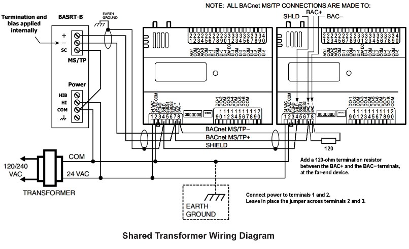
Automatedbuildings Com Article Using The Basrouter With A Honeywell Spyder Controller
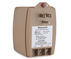
Honeywell 1361 Install Guide Alarm Grid
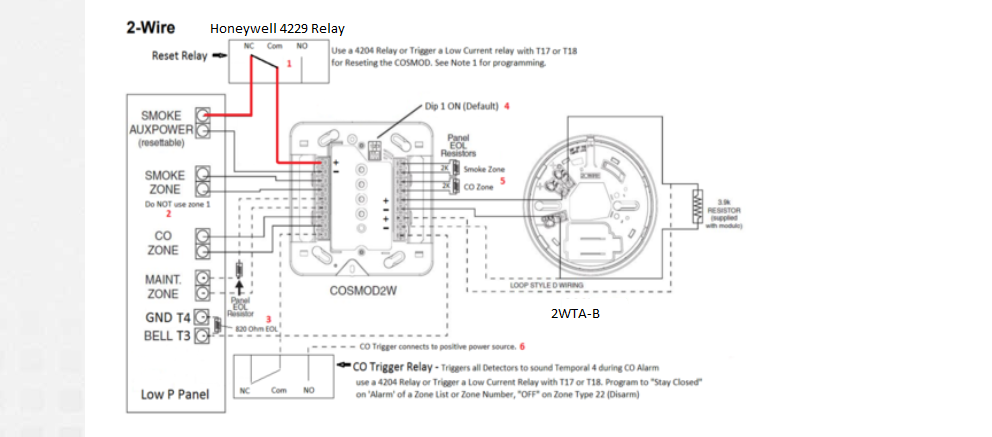
Honeywell 4229 8 Zone Wired Expansion Module With 2 Relays Alarm Grid
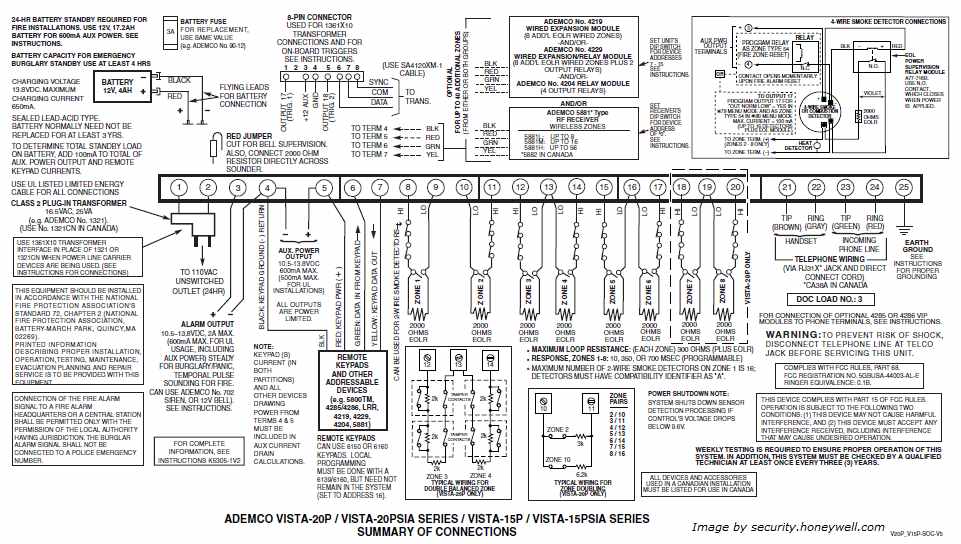
Ademco Vista 20p Wiring Diagram
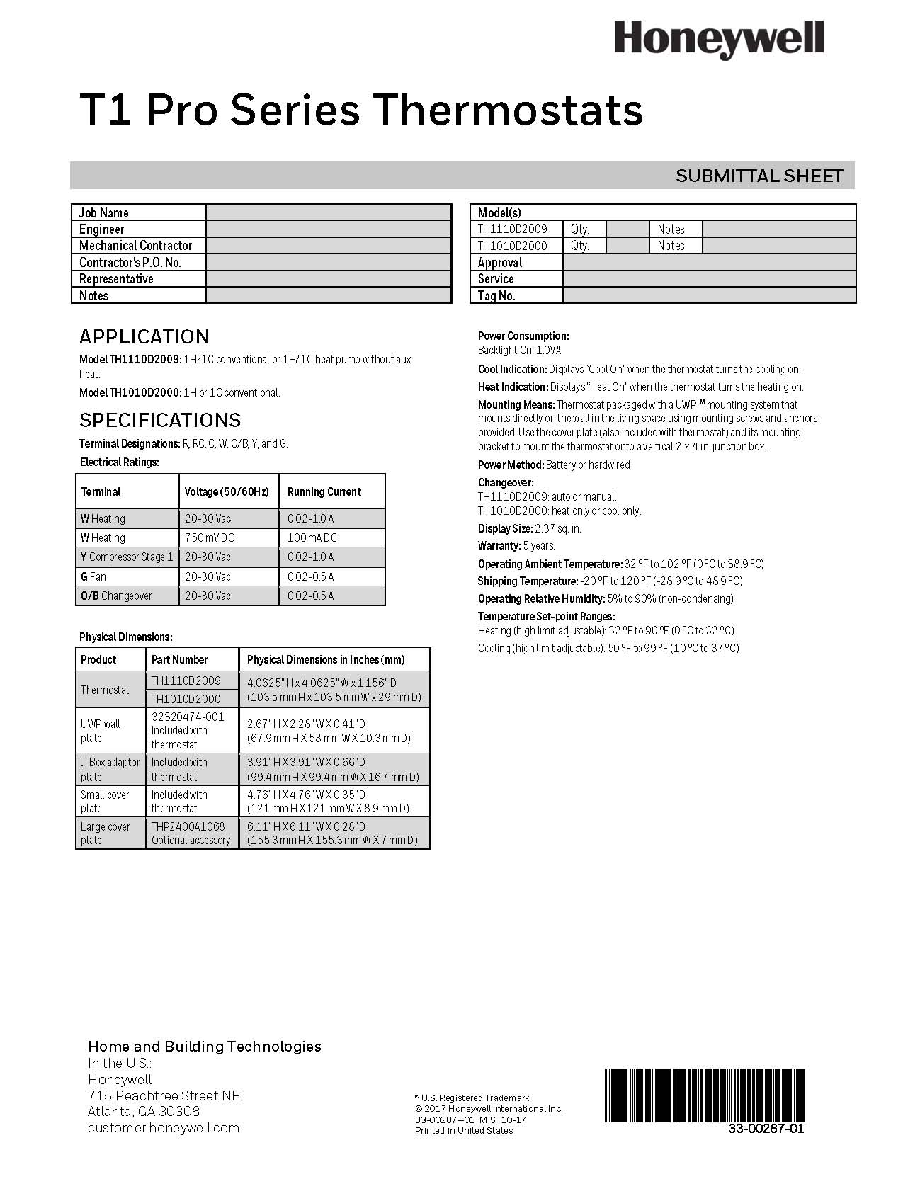
Honeywell T1 Thermostat Straight Cool Only Non Programmable 1h 1c Th1110d2009 Th1110d2009 U
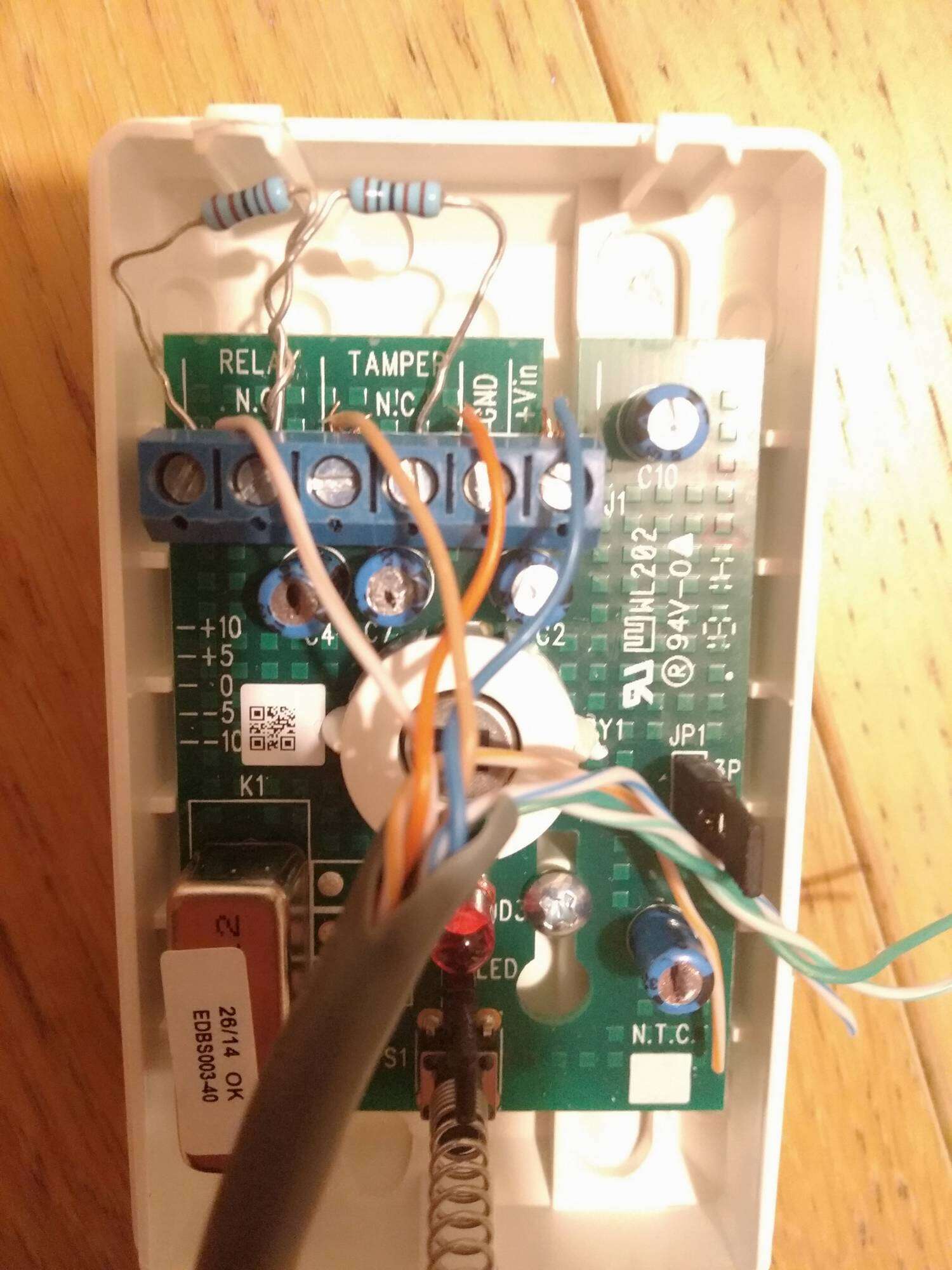
Help Understanding Eol Wiring Control Panels Public Security Installer Community
L4064b2236 U

How Do I Setup A 6160rf On A Honeywell Vista Alarm System Alarm Grid
Energies Free Full Text A Review On Flame Stabilization Technologies For Uav Engine Micro Meso Scale Combustors Progress And Challenges
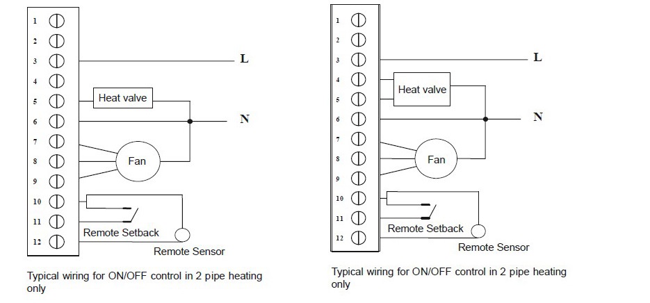
How To Wiring The Honeywell Digital Thermostat T6861

System Cabling For Controllers Pdf Pdf Electrical Connector Relay

How To Wiring The Honeywell Digital Thermostat T6861
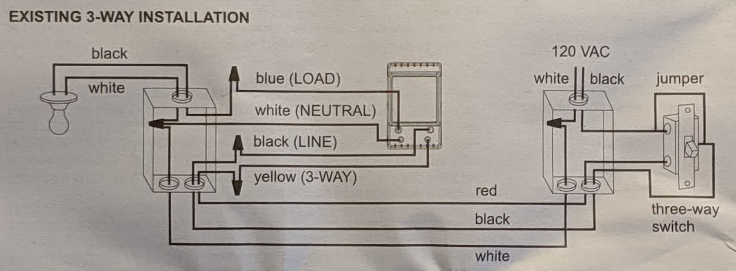
Wiring A Honeywell 3 Way Timer Switch Stephen Ostermiller

Honeywell 136434ba Eac Ionizer Wire Fits 16 Air Cleaner Amazon In Home Kitchen

Honeywell Ag6 Sounders Wiring Diagram For Two Sounder Boxs Electricians Forums Electrical Safety Advice Talk Electrician Forum
Vista 20p Installation Guide